网站运营建设岗位职责微信分销系统多少钱
threejs不仅支持各种texture的导入生成贴图,还可以利用canvas绘制图片作为贴图。这就用到了CanvasTexture,它接受一个canas对象。只要我们绘制好canvas,就可以作为贴图了。这里我们利用一张图片来实现这个效果。
基础代码:
import * as THREE from "three";
import { OrbitControls } from "three/examples/jsm/controls/OrbitControls";
import * as Dat from "dat.gui";
// 导入Three.js库
// import * as THREE from "three";// 创建场景、相机、渲染器等
const scene = new THREE.Scene();
const camera = new THREE.PerspectiveCamera(75,window.innerWidth / window.innerHeight,0.1,1000
);const renderer = new THREE.WebGLRenderer();
renderer.setSize(window.innerWidth, window.innerHeight);
document.body.appendChild(renderer.domElement);
const control = new OrbitControls(camera, renderer.domElement);// 创建立方体的几何体
const geometry = new THREE.BoxGeometry(3, 3, 3);// 创建动态Canvas并在其中绘制图像
const canvas = document.createElement("canvas");
canvas.width = 512;
canvas.height = 512;
const context = canvas.getContext("2d");
const image = new Image();
image.src = "src/assets/css.jpg"; // 替换为你的图片路径
image.onload = function() {context.drawImage(image, 0, 0, canvas.width, canvas.height);// 将Canvas创建为贴图const texture = new THREE.CanvasTexture(canvas);// 创建贴图材质const materials = [new THREE.MeshBasicMaterial({ color: "#f90" }),new THREE.MeshBasicMaterial({ map: texture }),new THREE.MeshBasicMaterial({ color: "#63a" }),new THREE.MeshBasicMaterial({ color: "#e2d" }),new THREE.MeshBasicMaterial({ color: "#c57" }),new THREE.MeshBasicMaterial({ color: "#f00" })];// 创建几何体网格对象const cube = new THREE.Mesh(geometry, materials);// 将网格对象添加到场景中scene.add(cube);
};// 设置相机位置
camera.position.z = 5;// 渲染场景
function animate() {requestAnimationFrame(animate);renderer.render(scene, camera);
}
animate();
最后的展示效果如下:
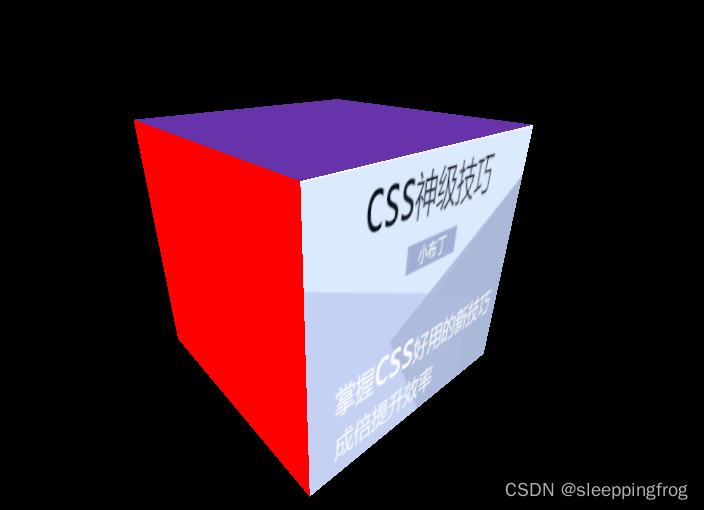
这里特别要注意贴图异步问题。在我们通过drawImage绘制图片的时候,sence.add(cube)这个操作要在img.onload()中执行,否则图片会无法展示出来