广州十大高端网站建设公司制作网页素材图片
macOS的MySQL有多种不同的形式:
1、本机包安装程序,它使用本机macOS安装程序(DMG)引导您完成MySQL的安装。有关详细信息,请参阅第2.4.2节,“使用本机包在macOS上安装MySQL”。您可以将包安装程序与macOS一起使用。用于执行安装的用户必须具有管理员权限。
2、压缩tar文件,它是使用Unixtar和gzip命令打包的文件。要使用此方法,您需要打开一个终端窗口。使用此方法不需要管理员权限;您可以使用此方法在任何地方安装MySQL服务器。
在macOS上安装MySQL的一般注意事项
您应该牢记以下问题和注意事项:
1、其他 MySQL 安装:本安装程序无法识别通过包管理器(如 Homebrew)安装的 MySQL。此安装和升级过程仅适用于我们提供的 MySQL 包。如果存在其他 MySQL 安装,请在执行此安装程序之前考虑停止它们,以避免端口冲突。
Homebrew :例如,如果你使用 Homebrew 将 MySQL Server 安装到了默认位置,那么官方的 MySQL 安装程序会将其安装到不同的位置,并且不会升级通过 Homebrew 安装的版本。在这种情况下,你会最终拥有多个 MySQL 安装,默认情况下它们会尝试使用相同的端口。在运行官方安装程序之前,请停止其他 MySQL Server 实例,例如通过执行 brew services stop mysql 来停止 Homebrew 的 MySQL 服务。
2、Launchd:启动守护进程
一个 launchd 守护进程已安装,它会修改 MySQL 的配置选项。如果需要,建议你编辑该守护进程的配置文件。有关更多信息,请参阅下方的文档。此外,macOS 10.10 及之后的版本移除了对传统启动项的支持,转而使用 launchd 守护进程来管理服务。macOS 系统偏好设置中的可选 MySQL 面板也依赖于 launchd 守护进程。
3、用户:您可能需要(或想要)创建一个特定的mysql用户来拥有MySQL目录和数据。您可以通过目录实用程序来执行此操作,并且mysql用户应该已经存在。对于单用户态,_mysql(注意下划线前缀)的条目应该已经存在于系统/etc/passwd文件中。
4、数据:因为MySQL安装程序将MySQL内容安装到特定于版本和平台的目录中,您可以使用它在版本之间升级和迁移数据库。您需要将data目录从旧版本复制到新版本,或者指定一个替代的datadir值来设置数据目录的位置。默认情况下,MySQL目录安装在/usr/local/下。
5、别名:您可能希望将别名添加到shell的资源文件中,以便更容易从命令行访问常用的程序,如mysql和mysqladmin。bash的语法是:
alias mysql=/usr/local/mysql/bin/mysql
alias mysqladmin=/usr/local/mysql/bin/mysqladmin
对于tcsh,使用:
alias mysql /usr/local/mysql/bin/mysql
alias mysqladmin /usr/local/mysql/bin/mysqladmin更好的是,将/usr/local/mysql/bin添加到您的PATH环境变量中。您可以通过修改shell的适当启动文件来做到这一点。
6、删除:从以前的安装中复制MySQL数据库文件并成功启动新服务器后,您应该考虑删除旧的安装文件以节省磁盘空间。此外,您还应该删除/Library/Receipts/mysql-中的旧版本的包收据目录。VERSION.pkg
使用本机包在macOS上安装MySQL
包位于磁盘图像(.dmg)文件中,您首先需要通过双击Finder中的图标挂载该文件。然后它应该挂载镜像并显示其内容。在继续安装之前,请务必使用MySQL管理器应用程序(在macOS服务器上)、首选项窗格或命令行上的mysqladmin关闭来停止所有正在运行的MySQL服务器实例。
要使用包安装程序安装MySQL步骤:
1、下载包含MySQL包安装程序的磁盘镜像(.dmg)文件。双击该文件以挂载磁盘映射文件并查看其内容。双击磁盘中的MySQL安装程序包。它是根据您下载的MySQL版本命名的。例如,对于MySQL服务器8.4.3它可能被命名为mysql-8.4.3-macos-。10.13-x86_64.pkg
2、初始向导引导您要安装的MySQL服务器版本。单击继续开始安装。MySQL社区版显示相关GNU通用公共许可证的副本。单击继续,然后单击同意继续。
3、在Installation Type页面中,您可以单击Install以使用所有默认值执行安装向导,单击Customize以更改要安装的组件(MySQL服务器、MySQL测试、首选项窗格、Launchd支持-除默认启用MySQL测试之外的所有组件)。尽管更改安装位置选项可见,但无法更改安装位置。
图2.5MySQL包安装向导:自定义
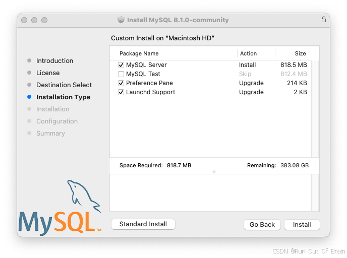
4、单击install按钮以开始安装MySQL服务器。如果升级当前MySQL服务器安装,安装过程将在此结束,否则按照向导的其他配置步骤安装新的MySQL服务器。
5、成功安装新MySQL服务器后,通过定义root密码并在启动时启用(或禁用)MySQL服务器来完成配置。
6、设置 root 用户密码并配置 MySQL 服务器是否在配置完成后自动启动
7、在 MySQL Server 安装完成后,概述(Summary) 是安装向导的最后一步。这一步确认了 MySQL Server 已成功安装并配置完毕。点击Close按钮关闭此向导
MySQL服务器现已安装完成。如果安装时您选择了不启动MySQL,则可以使用命令行中的Launchctl或通过使用MySQL首选项窗口中单击“开始”来启动MySQL。
在使用包安装程序进行安装时,文件会被安装到 /usr/local 目录下的一个与安装版本和平台名称相匹配的目录中。例如,安装文件 mysql-8.4.3-macos10.15-x86_64.dmg 会将 MySQL 安装到 /usr/local/mysql-8.4.3-macos10.15-x86_64/ 目录,并创建一个指向 /usr/local/mysql 的符号链接。下表展示了该 MySQL 安装目录的布局。macOS安装过程不会创建或安装示例my.cnf MySQL配置文件。
表2.6MySQLmacOS上的安装布局
| 目录 | 目录的内容 |
|---|---|
bin | mysqld服务器,客户端和实用程序 |
data | 日志文件,数据库,其中/usr/local/mysql/data/mysqld.local.err是默认的错误日志 |
docs | 帮助文档,如发行说明和构建信息 |
include | 包含(表头)文件 |
lib | 库 |
man | Unix手册页 |
mysql-test | MySQL测试套件(使用安装程序包(DMG)时,“MySQL测试”在安装过程中默认禁用) |
share | 其他支持文件,包括错误消息,dictionary.txt和重写SQL |
support-files | 支持脚本,如mysqld_multi.server、mysql.servermysql-log-rotate. |
/tmp/mysql.sock | Location of the MySQL Unix socket |
安装和使用MySQL启动守护程序
macOS使用启动守护进程来自动启动、停止和管理进程和应用程序,例如MySQL。
默认情况下,macOS上的安装包(DMG)会安装一个名为/Library/LaunchDaemons/com.oracle.oss.mysql.mysqld.plist的启动文件,其中包含类似于以下内容的plist定义:
<?xml version="1.0" encoding="UTF-8"?>
<!DOCTYPE plist PUBLIC "-//Apple Computer//DTD PLIST 1.0//EN" "http://www.apple.com/DTDs/PropertyList-1.0.dtd">
<plist version="1.0">
<dict><key>Label</key>             <string>com.oracle.oss.mysql.mysqld</string><key>ProcessType</key>       <string>Interactive</string><key>Disabled</key>          <false/><key>RunAtLoad</key>         <true/><key>KeepAlive</key>         <true/><key>SessionCreate</key>     <true/><key>LaunchOnlyOnce</key>    <false/><key>UserName</key>          <string>_mysql</string><key>GroupName</key>         <string>_mysql</string><key>ExitTimeOut</key>       <integer>600</integer><key>Program</key>           <string>/usr/local/mysql/bin/mysqld</string><key>ProgramArguments</key><array><string>/usr/local/mysql/bin/mysqld</string><string>--user=_mysql</string><string>--basedir=/usr/local/mysql</string><string>--datadir=/usr/local/mysql/data</string><string>--plugin-dir=/usr/local/mysql/lib/plugin</string><string>--log-error=/usr/local/mysql/data/mysqld.local.err</string><string>--pid-file=/usr/local/mysql/data/mysqld.local.pid</string><string>--keyring-file-data=/usr/local/mysql/keyring/keyring</string><string>--early-plugin-load=keyring_okv=keyring_okv.so</string></array><key>WorkingDirectory</key>  <string>/usr/local/mysql</string>
</dict>
</plist>
一些用户报告说,添加plist DOCTYPE声明会导致Launchd操作失败,尽管它通过了lint检查。我们怀疑这是一个n-粘贴错误。包含上述片段的文件的md5校验和d925f05f6d1b6ee5ce5451b596d6baed。
要启用启动服务,您可以:
1、打开macOS系统首选项并选择MySQL首选项面板,然后执行启动MySQL服务器。
图2.6MySQL首选项窗格:位置
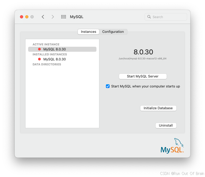
[实例]页面包含启动或停止MySQL的选项,初始化数据库重新创建data/目录。[卸载]卸载MySQL服务器和可选的MySQL首选项面板和启动信息。
图2.7MySQL首选项窗格:实例
2、或者,手动加载启动文件。
$> cd /Library/LaunchDaemons
$> sudo launchctl load -F com.oracle.oss.mysql.mysqld.plist升级过程将替换现有的名为com.oracle.oss.mysql.mysqld.plist的启动文件。
附加启动相关信息:
1、plist条目覆盖my.cnf条目,因为它们作为命令行参数传入。
2、在ProgramArguments部分定义了传递到程序中的命令行选项,在本例中是mysqld二进制文件。
3、默认的plist定义是在考虑不太复杂的用例的情况下编写的。对于更复杂的设置,您可能希望删除一些参数,而是依靠MySQL配置文件,例如my.cnf。
4、如果编辑plist文件,请在重新安装或升级MySQL时取消选中安装程序选项。否则,您编辑的plist文件将被覆盖,所有编辑都将丢失。
因为默认plist定义定义了几个ProgramArguments,所以您可以删除这些参数中的大部分,而是依靠您的my.cnfMySQL配置文件来定义它们。例如:
<?xml version="1.0" encoding="UTF-8"?>
<!DOCTYPE plist PUBLIC "-//Apple Computer//DTD PLIST 1.0//EN" "http://www.apple.com/DTDs/PropertyList-1.0.dtd">
<plist version="1.0">
<dict><key>Label</key>             <string>com.oracle.oss.mysql.mysqld</string><key>ProcessType</key>       <string>Interactive</string><key>Disabled</key>          <false/><key>RunAtLoad</key>         <true/><key>KeepAlive</key>         <true/><key>SessionCreate</key>     <true/><key>LaunchOnlyOnce</key>    <false/><key>UserName</key>          <string>_mysql</string><key>GroupName</key>         <string>_mysql</string><key>ExitTimeOut</key>       <integer>600</integer><key>Program</key>           <string>/usr/local/mysql/bin/mysqld</string><key>ProgramArguments</key><array><string>/usr/local/mysql/bin/mysqld</string><string>--user=_mysql</string><string>--basedir=/usr/local/mysql</string><string>--datadir=/usr/local/mysql/data</string><string>--plugin-dir=/usr/local/mysql/lib/plugin</string><string>--log-error=/usr/local/mysql/data/mysqld.local.err</string><string>--pid-file=/usr/local/mysql/data/mysqld.local.pid</string><string>--keyring-file-data=/usr/local/mysql/keyring/keyring</string><string>--early-plugin-load=keyring_okv=keyring_okv.so</string></array><key>WorkingDirectory</key>  <string>/usr/local/mysql</string>
</dict>
</plist>
在这种情况下,basedir、datadir、plugin_dir、log_error、pid_file和--early-plugin-load选项已从默认的plistProgramArguments定义中删除,您可以在my. cnf中定义他们。
安装和使用MySQL首选项窗口
MySQL安装包包括一个MySQL首选项窗口,使您能够在MySQL安装启动期间启动、停止和控制自动启动。
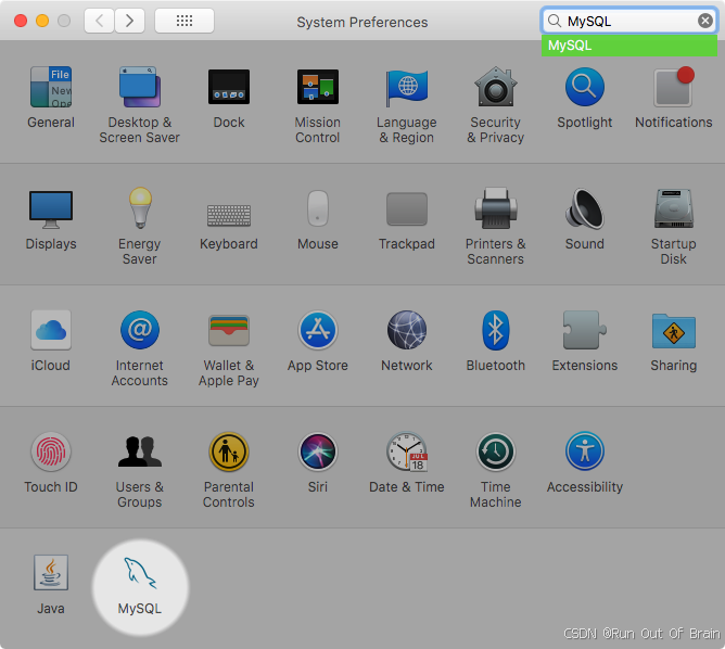
此首选项窗口是默认安装的,列在系统的系统首选项窗口下。
图2.8MySQL首选项窗格:位置

MySQL首选项窗格与安装MySQL服务器的DMG文件一起安装。通常它与MySQL服务器一起安装,但它也可以自行安装。
要安装MySQL首选项窗格:
1、完成安装MySQL服务器的过程
2、单击安装类型步骤中的自定义。此处列出了“首选项窗格”选项并默认启用;确保它没有被取消选择。可以选择或取消选择其他选项,例如MySQL服务器。
图2.9MySQL包安装向导:自定义

3、完成安装过程。MySQL首选项窗格仅启动和停止MySQL从已安装在默认位置的MySQL包安装安装的安装。
安装MySQL首选项窗格后,您可以使用此首选项窗格控制MySQL服务器实例。
[实例]页面包含启动或停止MySQL的选项,初始化数据库重新创建data/目录。[卸载]卸载MySQL服务器和可选的MySQL首选项面板和启动信息。
图2.10MySQL首选项窗格:实例

配置页面显示MySQL服务器选项,包括MySQL配置文件的路径。
图2.11MySQL首选项窗格:配置

MySQL首选项窗格显示MySQL服务器的当前状态,如果服务器没有运行,则显示已停止(红色),如果服务器已经启动,则显示正在运行(绿色)。首选项窗格还显示MySQL服务器是否已设置为自动启动的当前设置。